Layout of the display.
Making a Williams Pinball-Inspired Panaplex Clock
A word of warning before reading on: Panaplex displays require a high voltage (approx. 190V DC) to light! Replicate any panaplex display circuit at your own risk... mishandling the high voltage line can lead to fatal injuries.
If you want to add an arcade-style flair to your desk, try building this clock.
Follow the instructions below...
Let's get to know the display first...
Layout of the display.
This display is a Beckman SP-492 panaplex display. It was used as a score readout for many Williams pinball machines between 1977 and 1980.
Powering the display requires a strong high voltage supply. We need a 190V supply that can handle high capacity.
The answer to this problem is Omnixie's NCH6300HV Nixie tube power supply. This supply can handle a maximum load of 15W on the output!
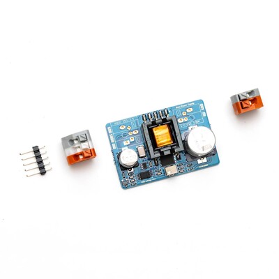
The NCH6300HV supply.
The next challenge is getting our 5V logic level signals to control the display. For this we will use MPSA42 and MPSA92 transistors. See below for how to wire them up...
Discrete transistor drivers for the display.
As you can see from above, the segment drivers use one MPSA42 transistor to pull the segments to ground with a 5V signal, and the digit drivers use a paired set of MPSA42 and MPSA92 transistors to pull the digit anodes to +190V when activated by a 5V signal.
To generate segment data we have two options of ICs... the MC14543 and the MC14558. Both are CMOS so use caution not to touch the pins without proper protection.
Below is a BCD to seven segment table of the MC14543...
Segment output table for MC14543.
You can see that the "6" has the top segment "A" and the "9" has the bottom segment "D" while the MC14543 is in use.
But what if we don't want those extra segments? We use the MC14558 instead. Have a look at the table for this IC...
Segment output table for MC14558.
We can see that, with the MC14558, we have removed both extra segments from the "6" and the "9".
We will use a DS1307 I²C RTC module for time keeping and memory here. A CR2032 battery will provide backup power to the module in the event of an outage.
An Arduino Pro Mini will be used to handle all the functions of the clock. This code will be needed to make the Arduino perform the necessary functions..
Now to put it all together. Follow either schematic below...
Schematic 1. Using the MC14543.

Schematic 2. Using the MC14558.
After the build, before applying power or installing the battery, upload the code to the Arduino. This will load the time into the clock.
To set the time, remove power and the backup battery, then reupload the code.
You should have something like shown below...
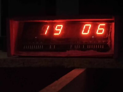
Result of the finished circuit.
Feel free to make a Williams pinball-inspired case to enclose the circuit!
Download link coming soon.
Contents