Layout of the VFD.
Making a Gottlieb Pinball-Inspired VFD Clock
Want a clock that will stand out on your desk or bedside table? Make this unique clock!
Follow the schematics as shown below to make it.
First off, let's get to know the VFD...
Layout of the VFD.
This VFD is Futaba's 4-LT-11, and was used in Gottlieb's System 1 pinball machines as the status display.
To power it, we need 3VAC on the filament (pins 1 and 32), and 40VDC (in multiplex drive mode) on the grids and segments.
But... how does one get AC from a DC supply? The answer: a simple oscillator circuit. See below for the schematic...
H-bridge oscillator circuit.
Gather two each of the following:
1k resistor
1.5k resistor
10k resistor
1µF capacitor
BC327 PNP bipolar transistor
BC337 NPN bipolar transistor
Then assemble the circuit as shown above. Power with 3.3V and you should have a faux AC output of 3V RMS.
The next challenge is getting our 5V logic level signals up to 40V... how to do that? Let's have a look at the UDN6118A...
Pinout of the UDN6118A.
What we do with this chip is we ground pin 9 and put our positive from our 40V supply on pin 10. This references the chip to 40V, so with any of the eight inputs at 5V, the corresponding output will output 40V.
For our segment data we will use the 74LS48. You probably know by now how to use this TTL decoder IC... here we are using only one decoder for this, and two 6118 source drivers (one for segments and one for grids).
Segment
output table for 74LS48.
To keep the time when power is cut to the circuit, we will use a DS1307 I²C RTC module. This provides a steady clock pulse to the circuit into a main processor to keep time. A CR2032 battery will provide backup power to the module when power is unavailable.
For the processor we will use an Arduino Pro Mini. We will need code on this device; it will be provided in this link as an entire copy-and-paste text page.
Now to put it all together. Follow the schematic below...
The full schematic.
Once the circuit is built, before applying power or installing the battery, upload the code to the Arduino. This will load the time into the clock.
To set the time, remove power and the backup battery, then reupload the code.
The result is shown below...
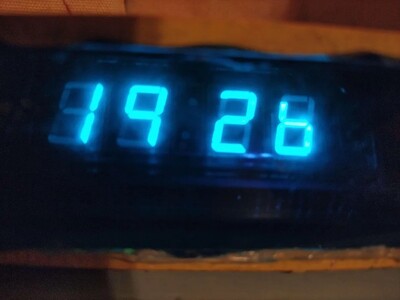
Result of the finished circuit.
Feel free to make a Gottlieb pinball-inspired case to enclose the circuit!
Download link for stencils here.
Contents